

 Current location:home > News Center > Company News >
 2023-04-19


PCB process flow 2: drilling
In the previous article, we introduced the PCB cutting process (click to learn more). This part comes to the PCB drilling process.
PCB drilling: Drill holes on the board surface according to routing or structural requirements.
Drilling process:
Double sided board drilling
Cutting process → Fixing with pins on the edge of the board → Adding aluminum sheet/upper pad → Drilling on the machine → Unloading the machine → Grinding the board → Hole inspection → Next process
Multilayer board drilling
Baking board → putting wooden board on → driving pipe position nails → adding aluminum sheet/putting on backing board → drilling holes on machine → getting off machine → grinding board → checking holes → finishing process
This time, we will take the "Double-sided PCB Drilling Process Steps" as an example to give a basic introduction to the drilling process.
01 PCB drilling - drilling preparation
Before using the drilling machine on the PCB production board, we need to understand the drilling structure and necessary preliminary preparations.
1. The role of each drilling structure
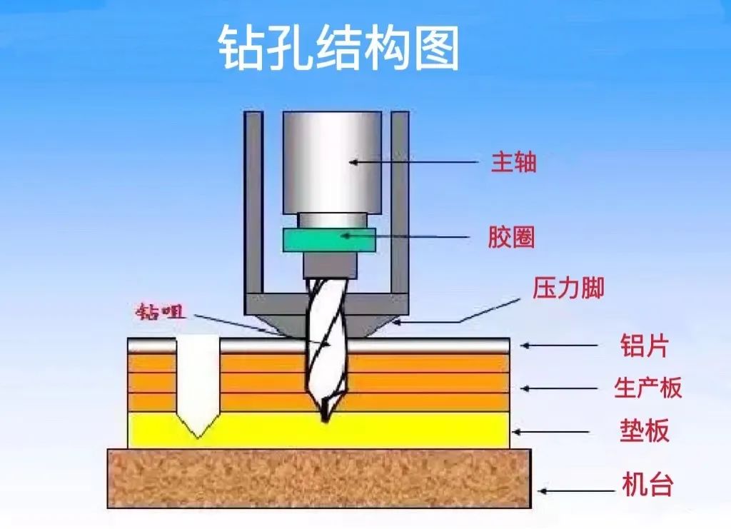
1) Spindle: The power source of the drill bit, which drives the drill bit to drill at high speed and provides the mechanical direction of the drill bit.
2) Rubber ring: controls the depth level of the drill bit.
3) Pressure foot: Press the board surface tightly when drilling.
4) Drill bit: for cutting copper clad board surface.
The quality of the drilling process not only depends on the accuracy of the drilling parameter settings, but also on the stability of the drilling machinery. We need to regularly inspect and update any structure to assist production operations.
2. Board edge pin fixation
In actual operation, the bare copper clad board cannot be fixed on the drilling rig, so we need to nail the edge of the production board.
In order to ensure high efficiency, not only one production board is fixed, but "single-hand boards" are stacked and fixed.
How thick is a "handboard"?
The thickness of the sheet that can be stacked is mainly determined by the blade length. Generally speaking, the stacking thickness requirement is within 4.8mm.
How to calculate the number of stacks of "one hand"?
The number of stacks can be determined by considering the following main factors:
1. Hole diameter (different drill bits have different blade lengths)
2. Sheet thickness
3. Total copper thickness
3. Protective equipment - upper aluminum plate and lower pad
After determining the thickness of the production plate, place an aluminum plate on top and a pad underneath, put the protection in place, and then drill holes on the machine. As shown in the figure:
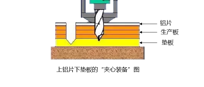
The aluminum sheet prevents the upper surface of the drill from being scratched, protects the plate surface (bruises, scratches, etc.), and plays a role in heat dissipation and improving drilling accuracy (preventing the blade from slipping during high-speed operation).
The pad can provide a certain thickness for the drill bit to act as a buffer when it reaches the bottom. It can protect the machine and prevent the bottom plate from being scratched.
02 PCB drilling - hole types
There are many ways to distinguish "holes":
1. According to the function of the hole: via, plug-in hole, copper-free mounting hole (Npth)
2. Based on the properties of the hole: plated hole (PTH), non-plated hole (NPTH)
3. According to the hole making method: blind hole, buried hole and through hole
1. Classification by the function of the hole:
Via, plug-in hole (Pad hole), copper-free mounting hole (Npth).
Via: It only serves as electrical conduction and does not require device insertion and soldering. There are three surface treatment methods: window opening (exposed pad), oil cover or oil plug.
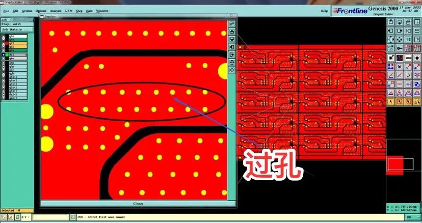
Via Diagram
Plug-in hole (Pad hole): The pin hole where the device needs to be soldered, the pad surface must be exposed
Non-copper mounting hole (Npth): Screw hole or plastic fixing foot of device, has no electrical performance and serves as positioning and fixing.
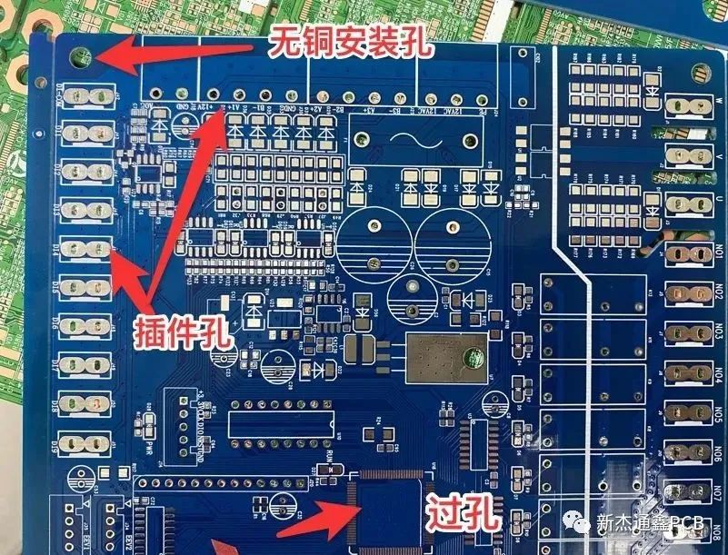
Types of holes Diagram 1
2. Classification by hole attributes:
a. Plated hole (PTH): also called metallized hole
b. Non-plated hole NPTH): also called non-metallized hole
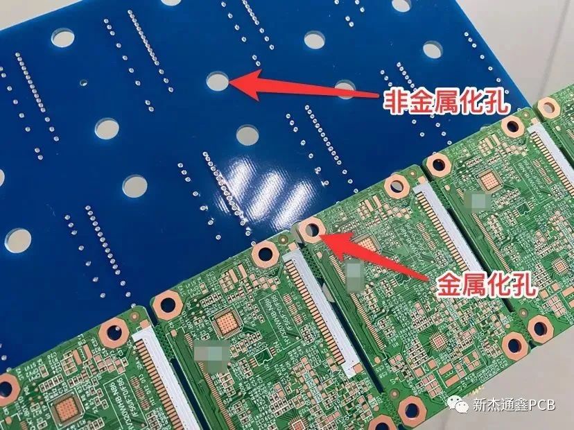
Types of holes Diagram 2
There are two types of hole definitions in the board factory, metal and non-metal. Most metal holes are device pin holes, and some are metal screw holes, which can be electrically conductive from top to bottom. Non-metal holes are holes without copper on the inner wall and are not conductive from top to bottom, also called mounting holes.
Note: For the same hole point, metal and non-metallized will affect the outer diameter, so the engineering drilling parameter data will be different.
3. Classification by hole making method:
Generally, they can be divided into three categories: blind vias, buried vias and through vias.
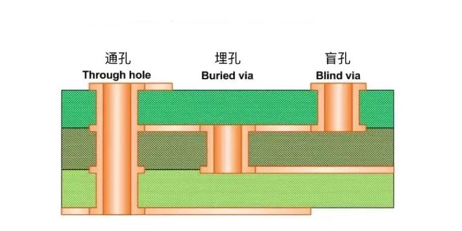
Types of holes Diagram 3
Through hole: Passes through the entire circuit board and is generally used for positioning and mounting components.
Blind hole: Located on the top and bottom surfaces of the printed circuit board, with a certain depth (the hole diameter and hole depth are in a certain ratio), used for connecting the surface circuit and the inner circuit.
Buried via: A connection hole in the inner layer of a circuit board (not visible on the surface of the circuit board). In this process, it is not possible to achieve this by drilling after bonding. Drilling must be performed on individual circuit layers. After partial bonding of the inner layer, electroplating must be performed before bonding can be completed. This is relatively more labor-intensive, requires more investment, and is relatively more expensive.
03 Holes with special functions—metal half holes
Metal half holes and stamp holes
Holes with special processes and functions: metal half holes and stamp holes.
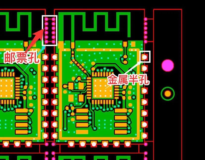
图3.1
Stamp holes:The so-called stamp holes in the board factory are copper-free holes that serve as bridges to separate boards. Stamp holes can be large or small, and the specific diameter and number of holes need to be determined according to the specific use location and needs (add more holes appropriately according to the size of the board and whether there are heavy components)
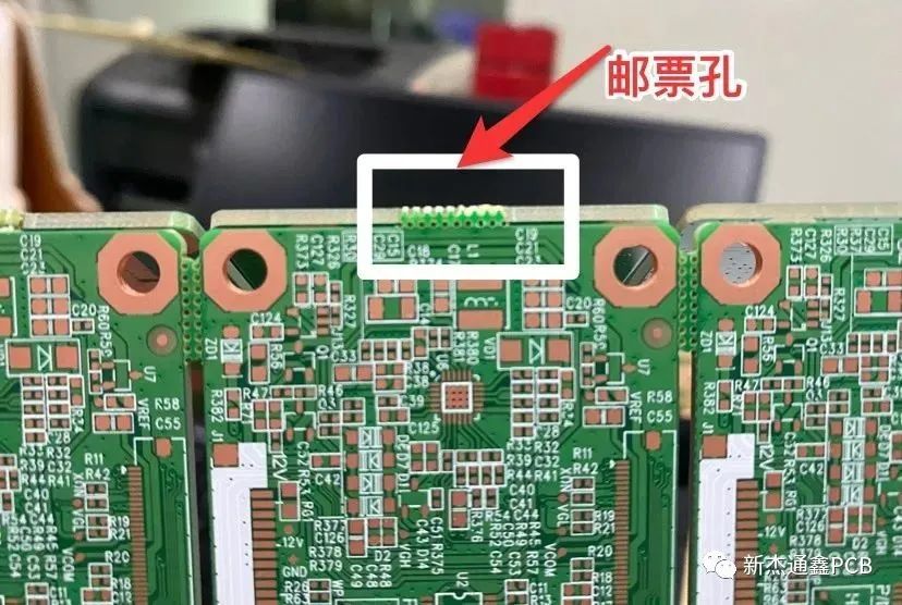
Figure 3.2
Metal half hole:The center needs to be drawn on the center of the outline, half inside the board and half outside the board. The minimum hole diameter of our company's half-hole process is 0.5mm.
The function of the metal half hole is generally for welding, and the position of the half hole is used to weld the plate with the half hole to another plate.
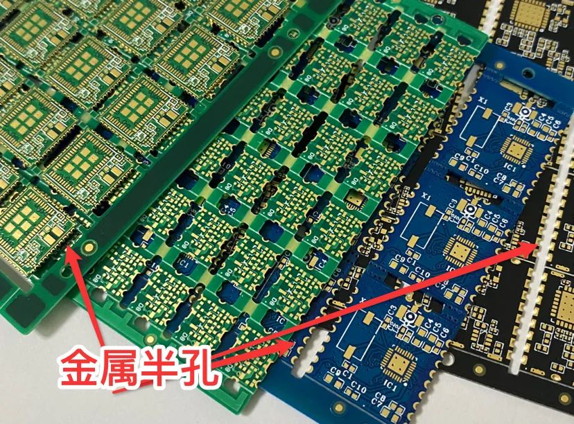
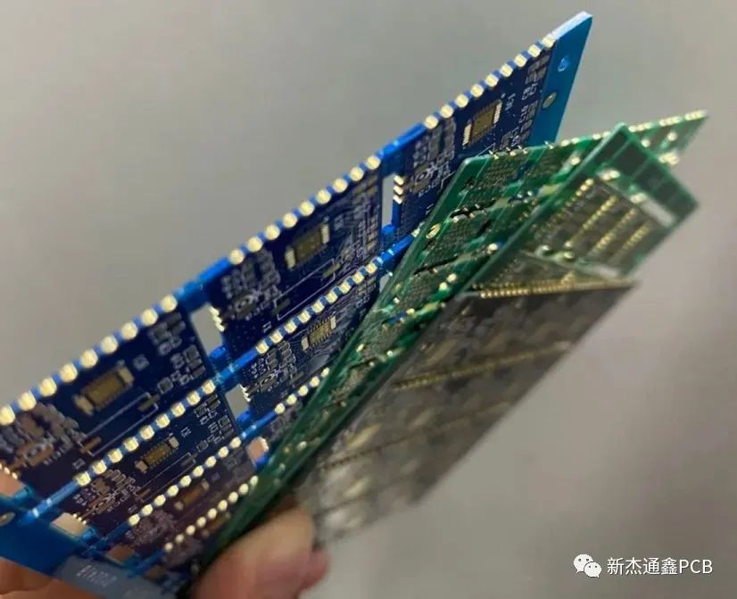
Figure 3.3
Xinjietongxin has a very mature process capability in manufacturing metal half-hole PCB boards, and has advantages in high reliability, difficult boards, and high-density circuit board products. We have already established in-depth cooperation with many module industry customers.
04 PCB drilling - hole inspection
After drilling and removing the machine, it must be polished to remove the edge and inspect the hole to prevent subsequent quality problems.
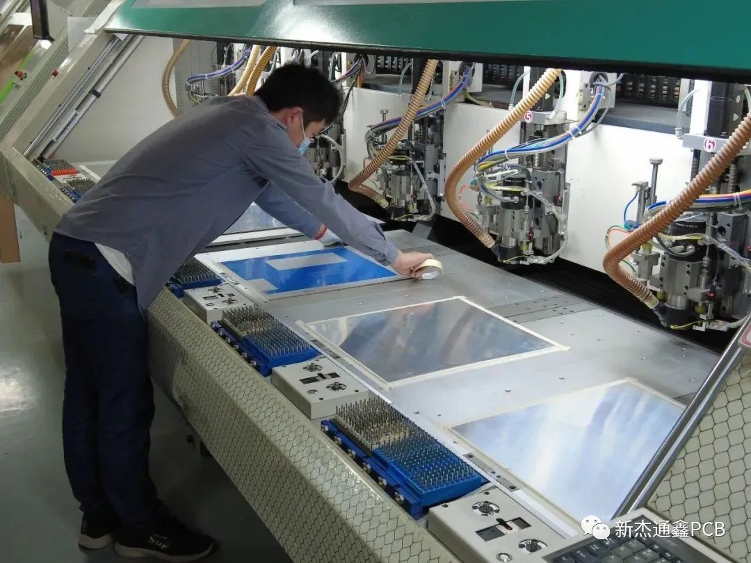
Especially with the rapid development of high-density boards, end customers have higher and higher requirements on the drilling process quality of PCB manufacturers. How to efficiently and accurately detect the drilling quality of PCB boards?
In order to improve the quality of drilling, Shenzhen Xinjietongxin Electronics Co., Ltd. has already adopted hole inspection machines on a large scale. Years of practice have proved that PCB hole inspection machines have become key supporting equipment, which can effectively improve the quality of drilling and final products.
We use the CCD image sensor of the hole inspection machine to perform efficient and stable drilling quality inspection.
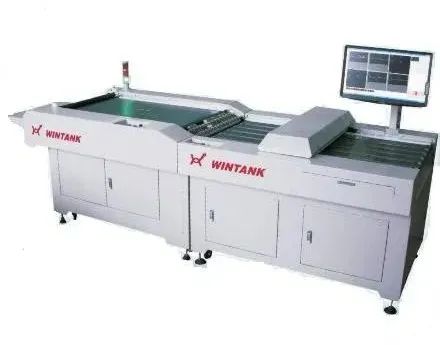
In routine inspections, we check multiple holes, few holes, large holes, small holes, and debris defects at the minimum hole diameter of 0.15mm and the speed of 7.5m/min. We also mark the locations of the defects and review the defect images to provide a basis for manual judgment.
The measurement accuracy is ±15μm, which can fully inspect even tiny debris, ensuring the high quality of our product manufacturing.
Summary
From the above, we can see that the more complex the drilling hole type and process, the higher the control difficulty and the higher the price of the circuit board.